Ce/ces/cero 12 208/240 v, ce/ces/cero 15 208/240 v, ce/ces/cero 18 208/240 v. An electronic low voltage elv dimmer used in conjunction with an led light emitting diode is almost a match made in heaven.

What is TRIAC Switching Circuit and Applications
Incandescent dimmer wiring diagram partial list of factory tested, compatible incandescent dimmers:

Triac wiring diagram. The triac electric actuators are factory set for 90 degree operation. The wire terminations are per the wiring diagram included with each package. Schematic iron soldering search easyeda.
Datasheet, pinout, equivalent [faq] bt136 is a type of electronic components, which is a triac. Need wiring diagram for thermo king tripac. The triac® apl series limit switches feature high quality, easy to use, multiple option switch boxes for rotary actuators.
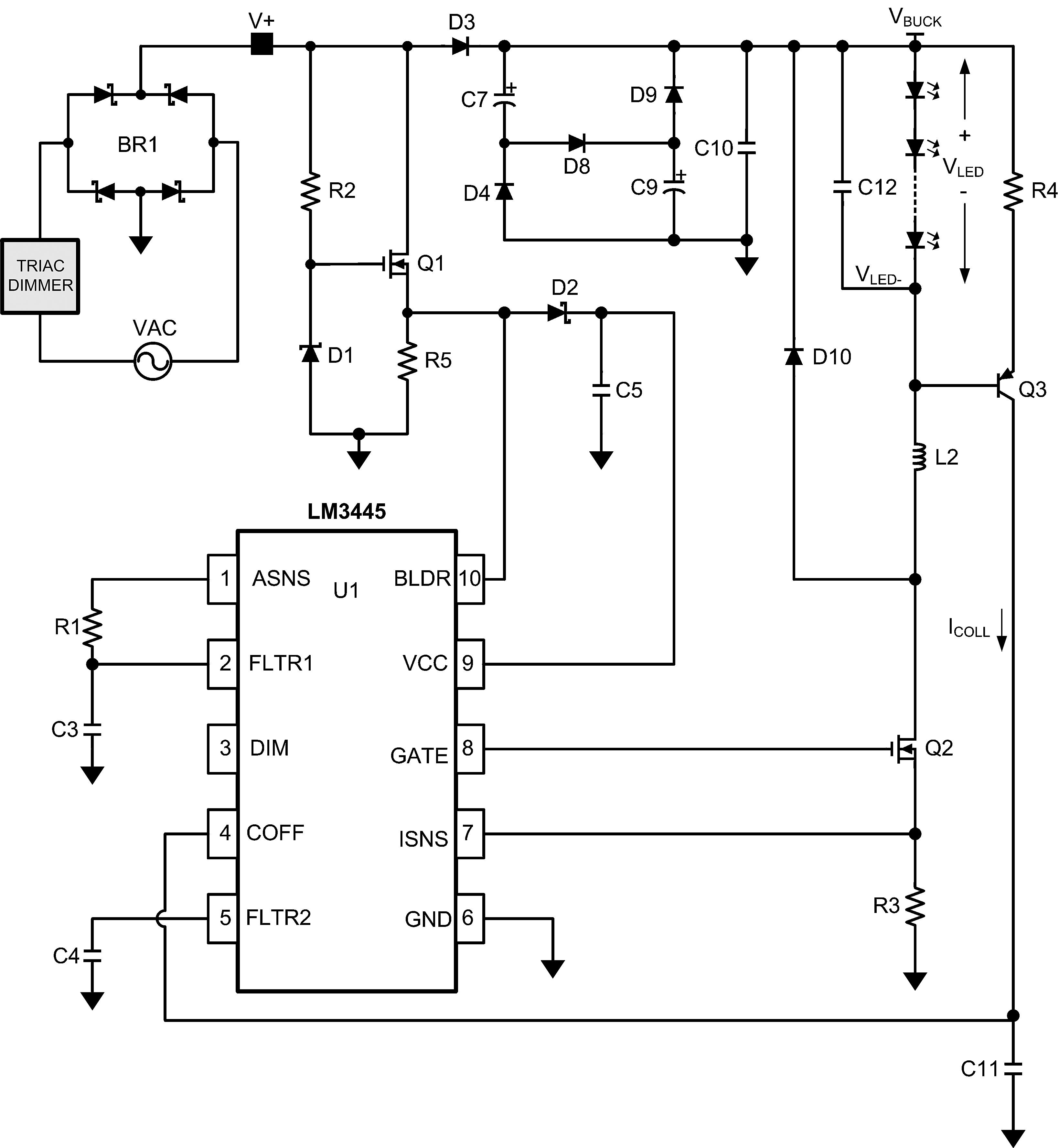
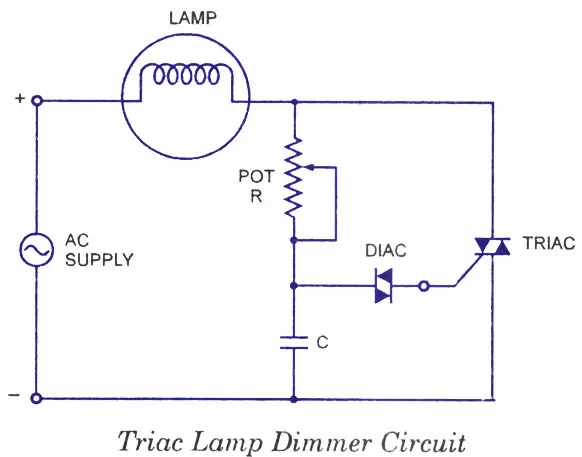
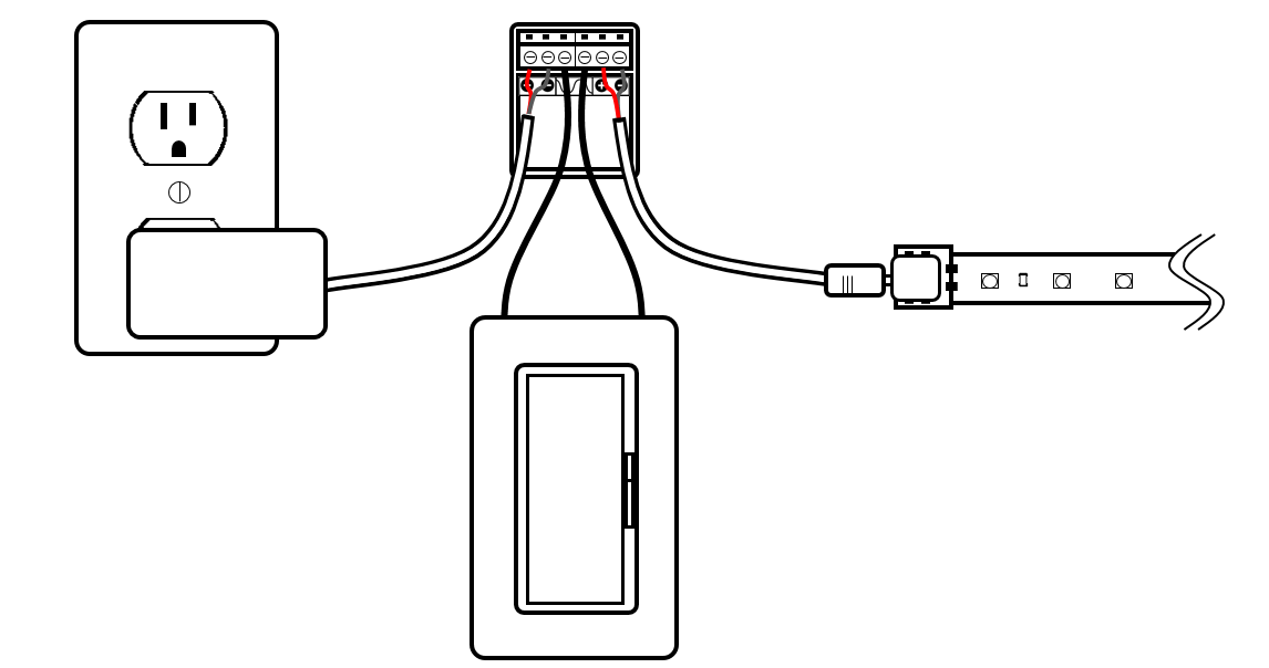
This is the simplest light dimmer circuit diagram or fan regulator circuit diagram. Triac dimmer led driver hot/line black common/neutral white white black triac dimming wiring diagram line voltage 120v 120v output led load low voltage dc wiring diagram powered by ltf ® l.t.f, l.l.c. Se1010 triac title block (1) author:
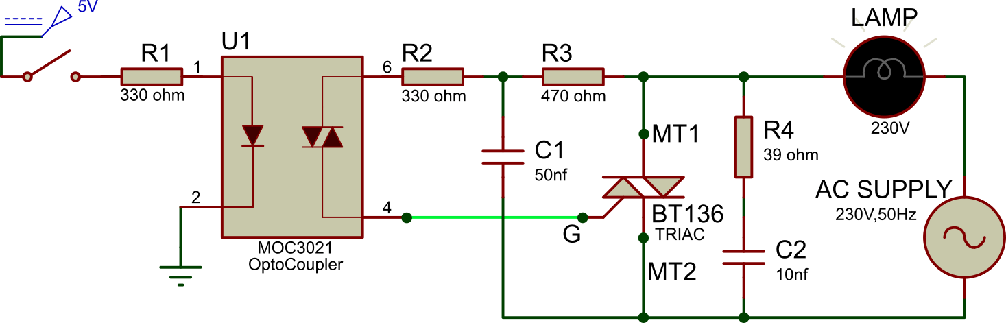
Ok sir,from the above diagram of bta41/600b triac,so which side to connect the triggering dc to triac diagram or how can i connect the dc 5v or 12v triggering to the same circuit with the ac bta41/600b.please sir indicate to me the place in the diagram. If you need a relay diagram that is not included in the 76 relay wiring diagrams shown below, please search our forums or post a request for a new relay diagram in our relay forum. The central element in this switching circuit is a triode alternating current switch, or triac.
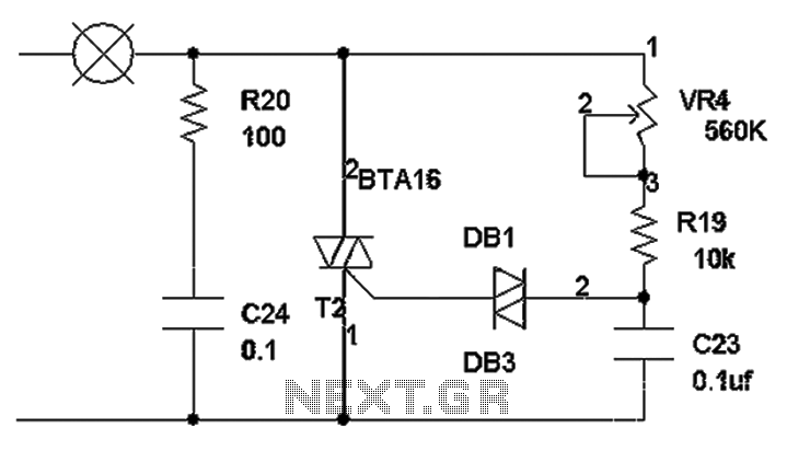
In the given circuit diagram a capacitor and a diac is connected in series with the gate terminal of a triac. The triac nanoshield can be used to control appliances connected to the power grid in 127v or 220v ac (alternating current) using the i/o pins of your arduino. A wiring diagram usually gives information more or less the relative face and concord of devices and terminals on the devices,.
Have older installation manual, but on unit all wires connects separate. Mount triac actuator to valve with triac provided mounting hardware to ensure. Thermo king tripac apu wiring diagram new wiring diagram load trail wiring diagram unique thermo king tripac is just one of the many collections of.
Dimmer can be installed on the line side load side or in the middle of the circuit. 90° iso5211 a 110vac 220vac 24vdc s4 lbs. In the last section, we saw that a dimmer switch rapidly turns a light circuit on and off to reduce the energy flowing to a light switch.
Wiring diagram single loop smart lighting control panel, replace traditional dimming knob, can be applied to small space of lighting control. The actuator should be wired and grounded in accordance with local and national electrical codes. Smart soldering iron adaptor temperature controller automatic switch from the q and a nuts volts magazine controlled 24v control circuit heat usb teardown irons complete guide rs use 220v with 110 v ac arduino hm 936d station diagram knock sensitive diy how to solder beginners my low level fun.
The following diagram show how to connect the triac nanoshield directly to an arduino uno or an arduino mega. The thyristor is also the abbreviation of the thyristor rectifier element. A triac is a small semiconductor device, similar to a diode or transistor.
The original product line of triac electric actuators, e series electric actuators offer torques from 300 to 30,000 in. Ac triac rf dimmer parameter wiring diagram product size feature •safe and reliable full isolation design •triac dimmable and mosfet dimmable •leading edge dimming and trailing edge dimming both available •great compatibility with a variety of remote controls •innovative minimum brightness setting function F03, f04, f05 2a.12.06.46 50% 90° 2.65
When the load pulls less current than the minimum triac holding current (to be discussed in a later section), the triac. Led magazine) this is an improvement over triac dimmers that are actually powered by the current flowing through them that is drawn by the led load (see figure 5). Universal slide dimmer project name.

How to Use Triacs for Controlling Inductive Loads like Transformers and AC Motors Circuit
Accu charger use a diac and triac Schematic Diagram under Repositorycircuits 23737 Next.gr
What is a Triac Triac Switch Electronics Notes


Triac SPDT Relay Circuit

Dimmer circuit using SCR TRIAC Electronic circuit projects, Electronics
What is TRIAC Switching Circuit and Applications

IR Remote Controlled TRIAC Dimmer Circuit Circuit, Circuit diagram, Electronics circuit
Triac dimming circuit diagram under Triac Circuits 59209 Next.gr
triac circuit Page 5 Other Circuits Next.gr
SIMPLE_TRIAC_CIRCUIT Control_Circuit Circuit Diagram

How to Use Triacs for Controlling Inductive Loads like Transformers and AC Motors Circuit

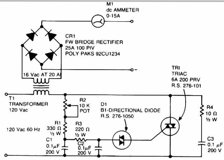
Triac Principles and Circuits — Part 1 Nuts & Volts Magazine Circuit, Electronics circuit

How to Use Triacs for Controlling Inductive Loads like Transformers and AC Motors Circuit
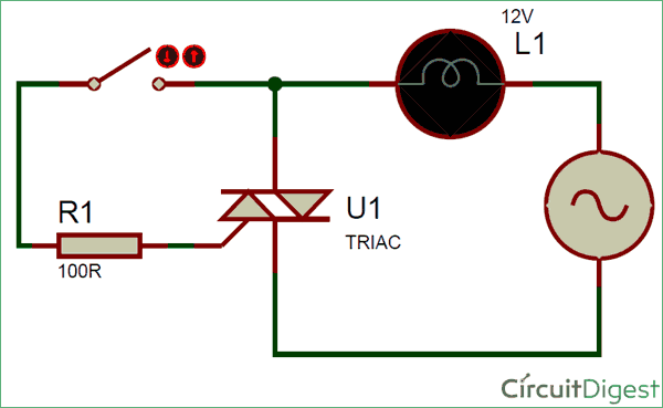
Switching AC Load Using Triac
Controlling TRIAC using DIGITAL pot for a 220v 500w dimmer

Simple Triac Dimmer Circuit Diagram and Electronic Circuits Projects

Triac Principles and Circuits — Part 1 Electronic schematics, Electronic circuit design, Circuit
Introducing the TRIAC Analyzer InspiredLED Blog
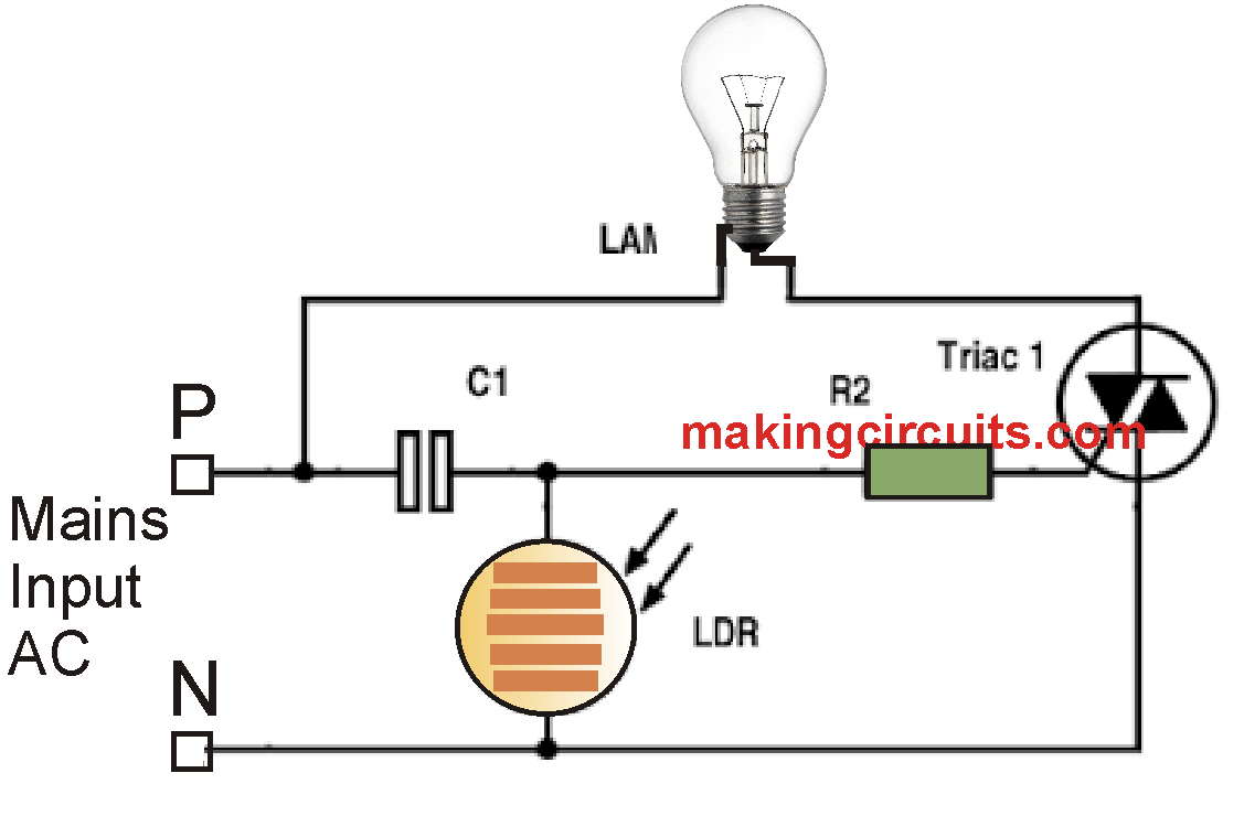
Day Night Activated Triac Switch Circuit