26/ 01/ 2022 1 the board 1.1 application examples the uno board is the flagship product of arduino. The atmega168 and atmega328 are pin compatible.
Arduino Uno Layout PCB Circuits
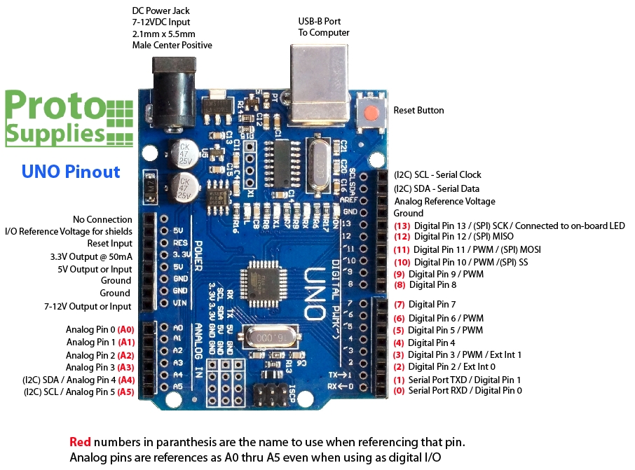
There is also a 2.1 mm dc jack to provide external power supply.
Arduino uno board layout. The uno's ground hole is connected to the blue column on the left of the board. Regardless if you are new to the world of electronics or will use the uno as a. Hi arduino people, where can i find the schematic and the board layout of the arduino uno r2.
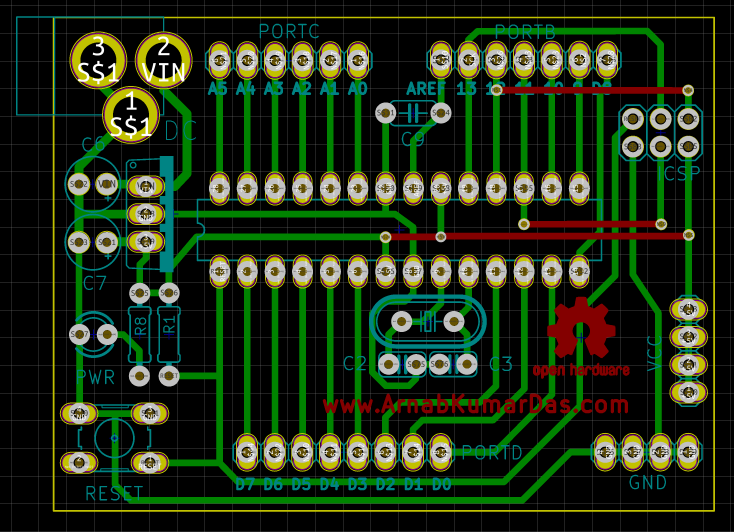
Arduino disclaims all other warranties, express or implied, arduino may make changes to specifications and product descriptions at any time, without notice. Anyway to use the most powerful functions you need. A 3d view / render of the pcb is also available in kicad.
Microcontroller section of diy arduino uno v1.0; 21 rows arduino uno is a microcontroller board based on the atmega328p. Eagle cad was used initially and later the file is imported into kicad.
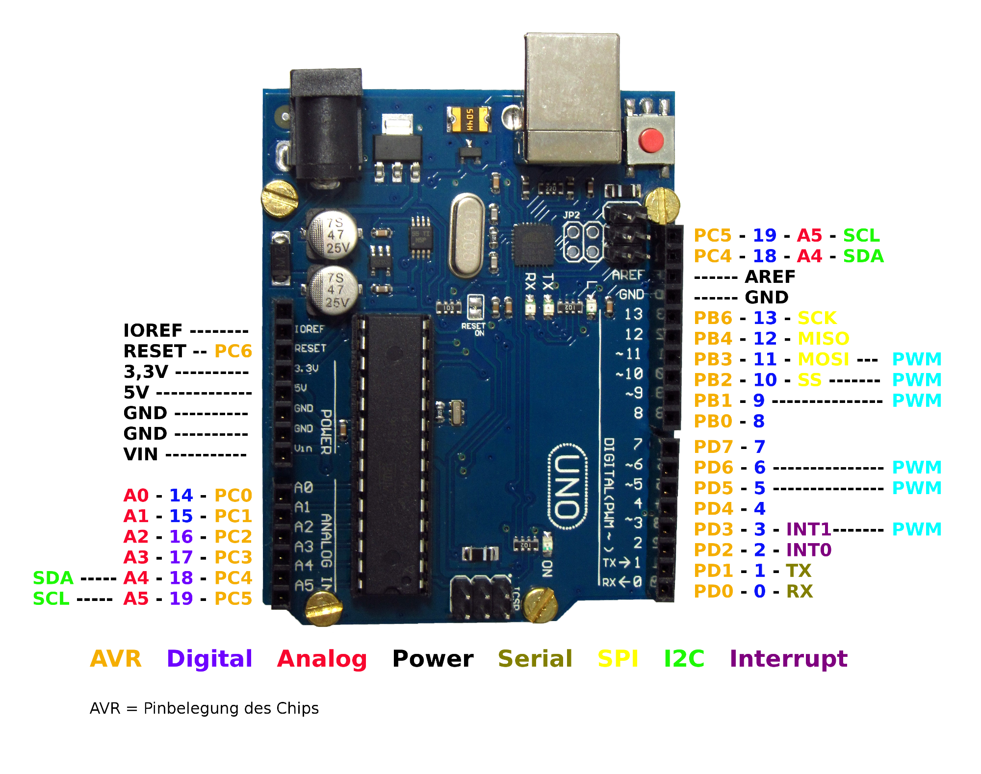
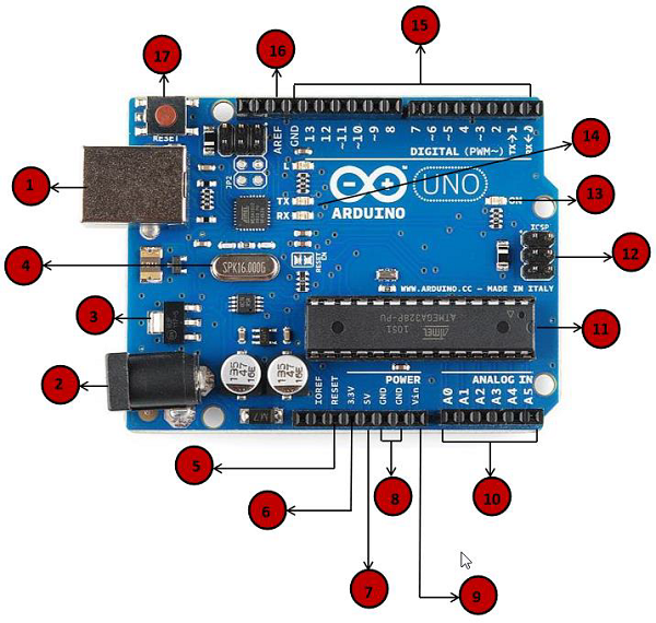
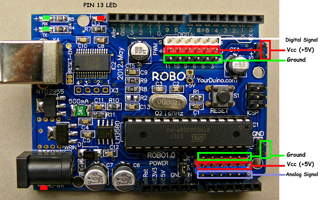
The arduino uno board is divided into digital pins, analog pins and power pins. An arduino uno on the left connected to a solderless breadboard, right. Pico is making big dreams of making small things a reality.
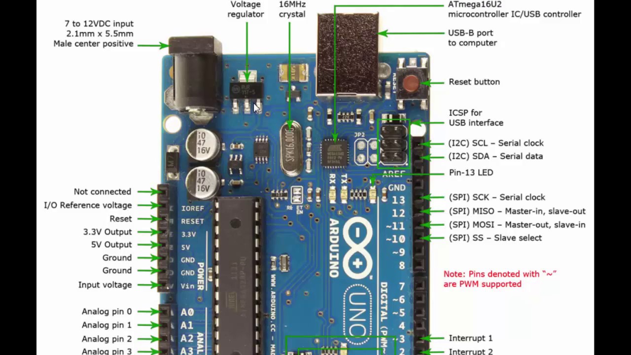
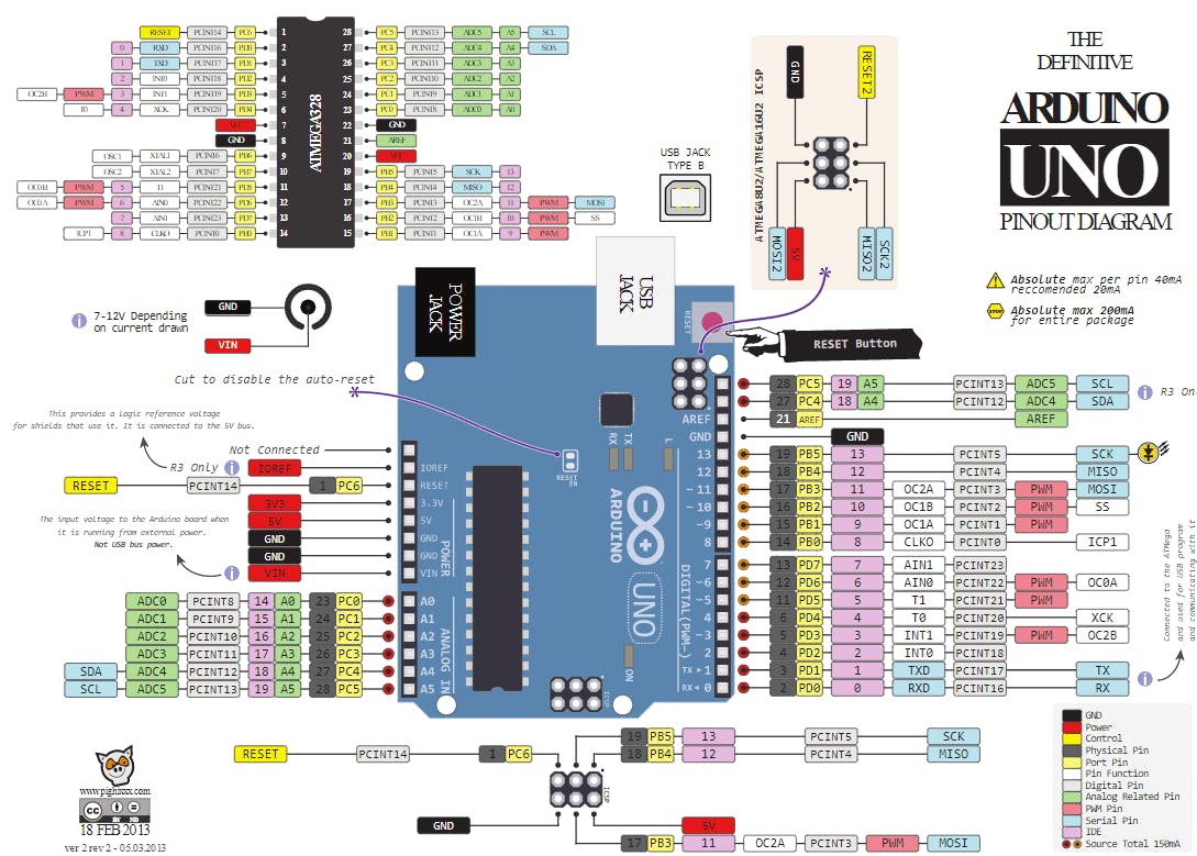
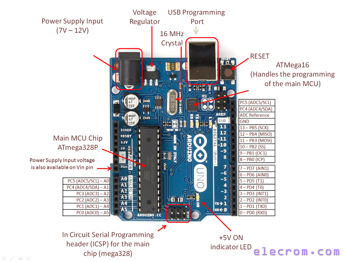
It has 14 digital input/output pins (of which 6 can be used as pwm outputs), 6 analog inputs, a 16 mhz crystal oscillator, a usb connection, a power. Along with atmega328p, it consists other components such as crystal oscillator, serial communication, voltage regulator, etc. These pins can read the signal from an analog sensor like the humidity sensor or temperature sensor and convert it into a digital value that can be read by the microprocessor.
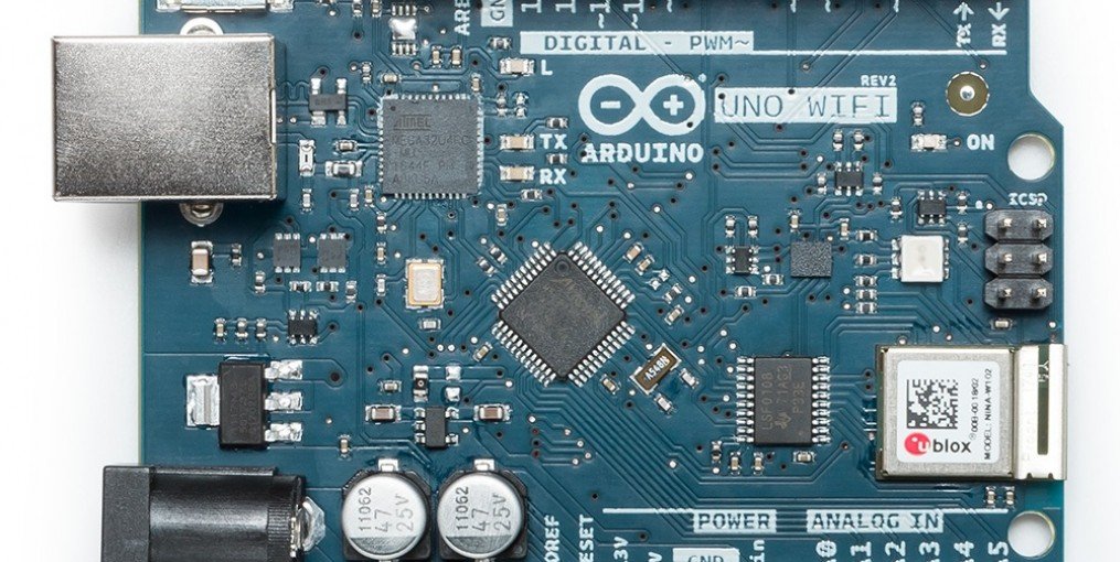
It contains everything needed to support the microcontroller; The new uno boards added a fourth mounting hole, which is indicated. Arduino® uno r3 4 / 1 3 ard u i n o ® u no r 3 m o d i fi ed :
Layout of arduino mega board. Each arduino board has its own microcontroller (11). Hope you all are doing good.
The drawing has dimensions for both the regular arduino and the arduino mega, and the hole pattern is good for all arduinos going back to the ng (though the diameter of the holes might be different). The uno's 5v output hole is connected to the red column of holes on the far left side of the breadboard. In this tutorial we will learn how to make your own arduino uno.
So please provide a link to the eagle files. Preparing the arduino ideto start, let go to tools > boards > boards manager and search for pico, select arduino mbed os rp2040 boards and hit the install button.connect the micro usb cable to the pico and then press and hold the bootsel button before plugging the usb cable into the computer. I bought a new uno r2 in the hope i could modify this open source hardware but i can't find the documentation.
Hello guyz, welcome to being engineers. Arduino uno reference design usb boot en tm reference designs are provided as is and with all faults. Arduino uno has 14 digital input/output pins (out of which 6 can be used as pwm outputs), 6 analog input pins, a.
Simply connect it to a computer. We saw that arduino boards are programmed using a language derived from c and c++ in arduino's integrated development environment (ide) and learned a few basic debugging methods.in this post, we'll be taking a closer look at the arduino hardware, and more. Arduino uno is a microcontroller board based on the atmega328p.
It has 14 digital input/output pins (of which 6 can be used as pwm outputs), 6 analog inputs, a 16 mhz quartz crystal, a usb connection, a power jack, an icsp header and a reset button. Arduino/genuino uno is a microcontroller board based on the atmega328p ( datasheet ). The arduino uno is a microcontroller board based on the atmega328.
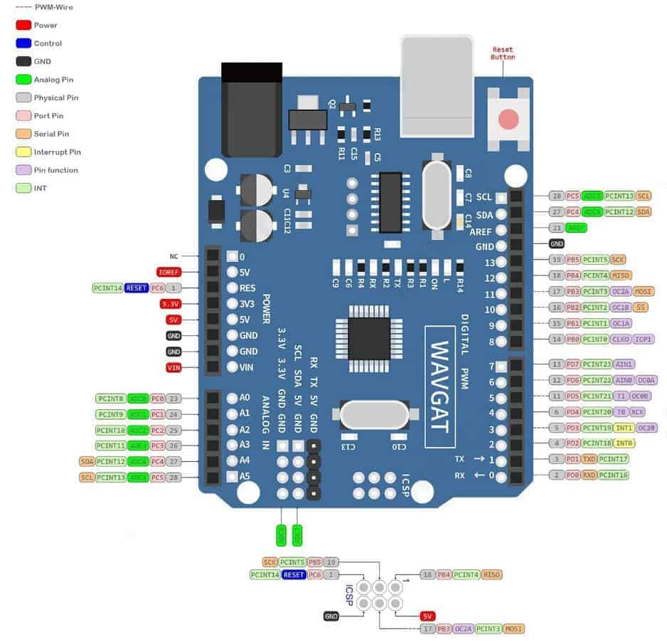
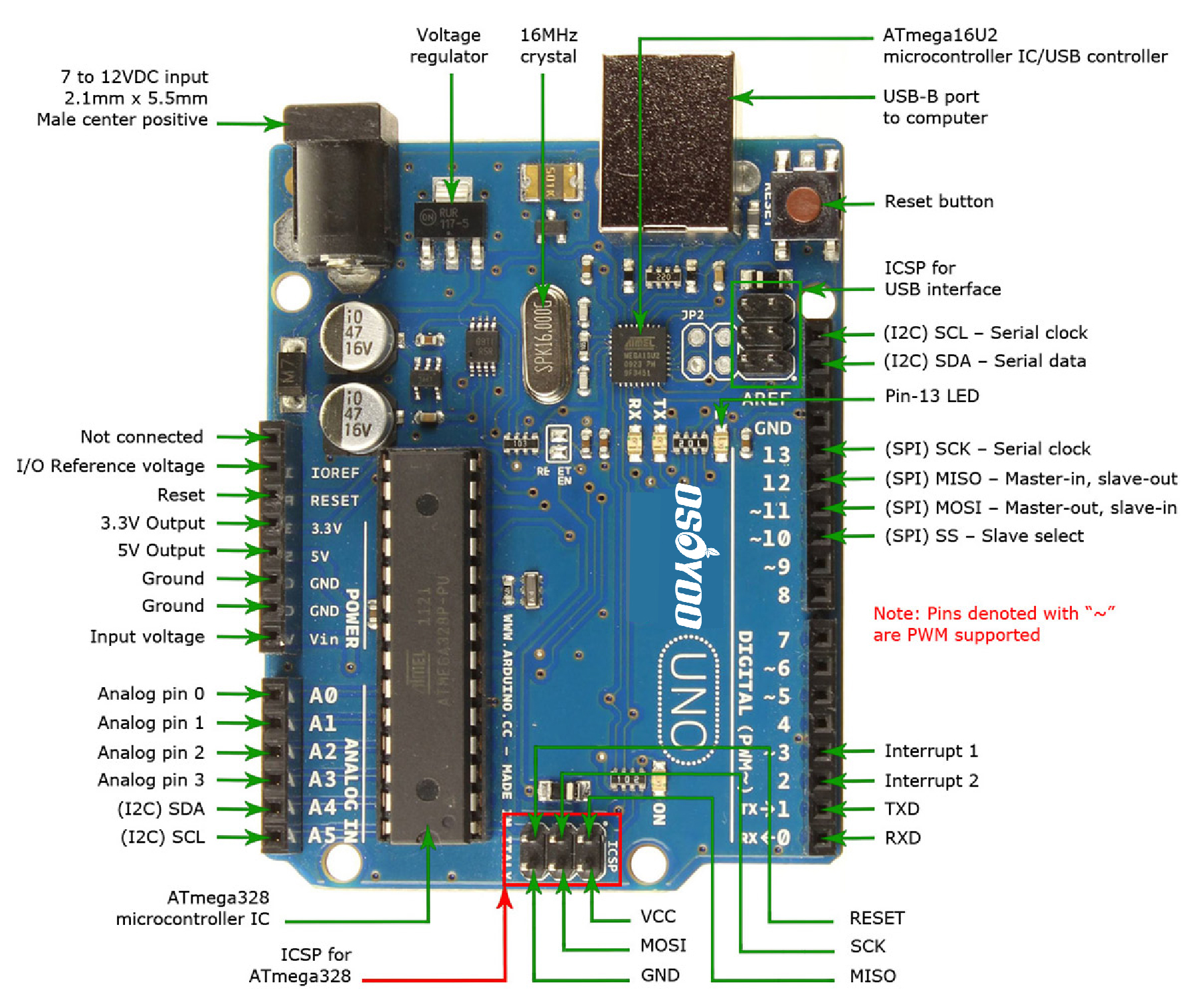
There are pins with secondary functions as listed below. The arduino uno board has six analog input pins a0 through a5. We will gather the components, test the circuit in breadboard, then we will make the board itself.
Atmega168 pinout with arduino labels; Diy arduino uno v1.0 schematic design pcb layout. Similar steps are followed for the pcb layout as it is followed for schematic capture.
Secondary pins are mostly communications pins such as i2c and spi. Schematic (you can see an arduino's uno r3 board schematic screenshot) board (the pcb editor) which can be seen "in action" which shows the pcb of the arduino's r3 board for people used to the other similar cads, the interface is very closed to them and you'll learn to use it easily; These pins are connected to the analog header on the arduino board.
In our last two posts, we focused on the software aspects of the arduino. It has 14 digital input/output.
Arduino Uno R3 Components Layout Circuit Boards

Arduino Uno Board Pin Layout Pcb Circuits

Architecture of Arduino UNO Board Download Scientific
Arduino Uno Component Layout Circuit Boards
Arduino Uno pin out discription TEACH TECH MAGZ
Arduino Uno R3 Board Layout PCB Circuits
Arduino Uno R3


Arduino Uno Board Pcb Layout PCB Circuits

Arduino Uno R3 Board ගැන දැනගනිමු. Buy and Learn Arduino

Arduino Uno Rev3 Arduino Official Store
Uno R3 SMD (Arduino Compatible) ProtoSupplies

Arduino Uno For Beginners Projects, Programming and
Arduino Uno R3 from Wavgat
Introduction to Arduino UNO (uses AVR ATmega328
DIY Arduino UNO v1.0 Schematic and PCB Layout Arnab
OSOYOO UNO Board — Fully compatible with Arduino UNO Rev.3

Arduino Uno Pcb Layout Proteus Pcb Circuits
QuickRef ArduinoInfo
Arduino ArduinoBoardUnoSMD


